
Tilt Correction and the Tilt Correction Advisory
This guide is a self-contained walk-through for measuring and correcting sensor tilt in Ekos, from initial setup through iterative correction to verification. It builds on the Aberration Inspector in the Focus module and focuses on the Tilt Correction Advisory, which translates measured tilt into concrete mechanical adjustments, and on its integration with motorized tilt plates such as the WandererAstro ETA M54.
Overview — What is Sensor Tilt?
When the imaging sensor is not perfectly perpendicular to the optical axis, different regions of the field come to focus at different distances from the flattener/corrector. This manifests as:
Stars in one corner appearing sharper than the opposite corner.
Uneven HFR values across the field after autofocus.
One side of the image always appearing slightly out of focus.
Uneven color-correction performance across the frame — because each region sits at a different distance from the correcting lens element, chromatic correction (and field flatness) is optimized for only part of the sensor, so color fringing can be stronger on the side that is furthest from the ideal focal plane.
The Aberration Inspector measures this tilt by running autofocus across multiple regions (tiles) of the sensor simultaneously. The focus-position difference between tiles, converted to physical microns using the focuser step size, reveals the tilt magnitude and direction. The Tilt Correction Advisory then translates these measurements into concrete mechanical adjustments — telling you which screws to turn, and by how much.

Imaging train with a WandererAstro ETA M54 tilt plate installed between the focuser and the camera.

The WandererAstro ETA M54 Electronic Tilt Adjuster (front view). The three motorized adjustment points are labeled "1", "2", and "3"; each arm houses a stepper motor with an encoder. The M54 threaded side faces the telescope/focuser. The sensor side has 6 screw holes for bolting adapters directly (optional threaded adapters are available). In this photo a Pegasus Astro Indigo OAG with helical focuser is attached. Note that not all OAGs fit inside the ETA's central opening — the Svbony OAG neck, for example, is too wide, while the Pegasus Indigo OAG fits.
Prerequisites
Hardware
A telescope with a field flattener/corrector.
An electronic (absolute) focuser, e.g. ZWO EAF, Pegasus FocusCube, MoonLite.
A tilt adjustment plate:
3-point motorized: WandererAstro ETA M54 (recommended — allows automated apply).
3-point manual: Octopi, manual 3-screw tilt rings.
4-point manual: ToupTek M42 Tilter and similar push/pull plates.
A star-rich field for measurement (open clusters work well: NGC 2516, M44, M67).
Software / configuration
KStars 3.8.4 or later (the Tilt Correction Advisory and ETA integration are merged upstream).
For ETA integration: the INDI driver
indi_wanderer_eta.The Mosaic Mask enabled in the Focus module.
Focuser step size correctly configured (see the next section).
The optical train set up in Ekos (sensor dimensions and pixel size are read automatically from the camera driver).
The ETA connected as an Auxiliary device in the Ekos profile (if using automated apply).
Measuring Focuser Step Size
The focuser step size (microns per step, µm/step) is critical for accurate tilt measurements. The Aberration Inspector converts focuser tick differences between tiles into physical distance (microns). If this value is wrong, the tilt magnitude will be scaled incorrectly (although the direction will still be correct).
Where to configure
In the Focus module, open the CFZ dialog (Critical Focus Zone). The Step Size
field specifies how many micrometers the focuser moves per single step (tick).

The Focus CFZ dialog: step size is set to 2.754 µm for this ZWO EAF + Askar SQA130 combination. The CFZ calculation (18 µm = 7 steps) uses this value.
How to measure
If your focuser manufacturer publishes a specification, use it. Typical values:
ZWO EAF: ~1.5–3.0 µm/step (depends on the scope's focuser mechanism).
Pegasus FocusCube: ~2.0–5.0 µm/step.
MoonLite: varies by model.
If no specification is available, or you want to verify it, use the full-travel method:
Measure the physical travel. With the focuser disconnected from the scope, use a digital caliper or dial indicator against the drawtube. Mark the fully retracted and fully extended positions and measure the total travel in mm.
Count the total steps. Drive the focuser from one end to the other using the INDI control panel and note the step count for the full travel.
Calculate.
Step Size (µm/step) = (Total Travel in mm × 1000) / Total Steps.
Example (ZWO EAF on Askar SQA130): total travel ~31 mm, total steps ~11,250 → 31,000 µm / 11,250 = 2.76 µm/step.

Drive the focuser through its full travel, measure the physical distance, and divide by the step count.
Why it matters
Consider a sensor with 50 µm of tilt. The focus module might report a 20-tick difference between the left and right tiles.
With the correct step size (2.5 µm/step): 20 × 2.5 = 50 µm → correct advisory.
With a wrong step size (5.0 µm/step): 20 × 5.0 = 100 µm → advisory overshoots 2×.
The direction of the correction is right either way, but a wrong step size makes you overshoot or undershoot the magnitude on each iteration, requiring more passes to converge.
Running the Aberration Inspector
Achieve focus first. Before using the Aberration Inspector, run a normal autofocus on the full image (no mosaic mask) to bring the focuser near the correct position. You need a good V-curve with a clean solution — the Aberration Inspector sweeps around the current focus position, so if you are far from focus the tiles will not produce usable data.
Switch to the Mosaic Mask. The mask is selected in the Focus module's settings. Open the Focus Options and find the Mask selector — it offers Use all stars (full image, the default for normal autofocus), Ring Mask, and Mosaic Mask. Choose Mosaic Mask for tilt measurement. Adjust the tile size so each tile captures enough stars (tiles around 256–512 px work well for most setups).
Point to a star-rich field. Open clusters are ideal. Avoid nebulae or regions with few stars — you need multiple stars in every tile for reliable curve fits.
注釈
Choosing a good spot in the sky. Tilt measurement depends on clean, round star shapes and steady tracking across the whole sweep. For best results: pick a region with clear, well-separated stars and good contrast; ensure good mount performance, since tracking errors or drift during the sweep distort the per-tile HFR; and avoid areas where the mount tracks poorly. Targets very close to the zenith or right on the meridian can be problematic (near the zenith, small tracking moves cause large apparent motion; on the meridian, some mounts track less smoothly near the balance point). A field at a moderate altitude, well away from these, tends to give more consistent star shapes for measurement.
Click "Aberration Inspector". In the Focus module's Tools section, click the
Aberration Inspectorbutton. This starts a dedicated tiled autofocus run that sweeps through focus positions while measuring HFR in each mosaic tile independently.Tip
Consider using a larger step size for the Aberration Inspector run than for your normal autofocus. Because each tile has fewer stars, the per-tile V-curves can look bumpy with small steps; larger steps produce smoother curves and more reliable tile solutions.
Wait for completion. When all tiles' V-curves are fit, the Aberration Inspector dialog appears automatically with the results.
注釈
The Tilt Correction Advisory section within the Aberration Inspector is only visible when either (a) a WandererAstro ETA is detected as connected, or (b) you manually enable the Tilt Plate checkbox in the Aberration Inspector toolbar. Otherwise the advisory panel stays hidden.

Focus module after a successful Aberration Inspector run: 56 stars detected, HFR 1.32,
R²=0.99. The mosaic mask grid is visible on the star field (right). The
Aberration Inspector button in the Tools section triggers the tiled measurement run.
Understanding the Results
The Aberration Inspector presents a per-tile table, a set of summary values, and a multi-tile V-curve graph. (See the Aberration Inspector reference in the Focus documentation for the full description of every control.)
Tile table — each row is a mosaic tile (region of the sensor): the focus
Solution (steps), Delta (ticks) and Delta (µm) relative to the centre tile,
the Num Stars used vs. detected, and the R² goodness-of-fit.
Summary values
Backfocus Δ— how far the sensor is from optimal backfocus distance (± µm).Left-Right Tilt— tilt along the horizontal axis (µm and %).Top-Bottom Tilt— tilt along the vertical axis (µm and %).Total Tilt— combined vector magnitude (µm and %).
Multi-tile V-curve — all tiles' V-curves overlaid. In a tilted sensor the curves are shifted horizontally relative to each other; the minimum of each curve occurs at a different focuser position.

Aberration Inspector showing all 5 tiles (TL, TR, C, BL, BR). The TL curve (red) diverges significantly from the others, indicating the top-left region is further from ideal focus. Total tilt: 30 µm. The 3D visualization (right) shows the tilt plane.
Tilt Correction Advisory
Below the measurement results, the Tilt Correction Advisory translates the raw measurements into specific mechanical adjustments.
Configuration
Setting |
Description |
Example |
|---|---|---|
Plate |
3-point or 4-point geometry |
3-point |
Radius |
Bolt-circle radius in mm (centre to screw) |
64.0 mm (ETA M54) |
Thread |
Screw thread type (determines pitch) |
Wanderer ETA (0.50 mm) |
Pitch |
mm per full turn of the adjustment screw |
0.50 mm/turn |
Rotation |
Camera body rotation (visual aid only) |
0° or 10° |
Mode |
How corrections are presented |
Push-only (from zero) or Relative (± deltas) |
注釈
Setting the radius and thread for your plate. The radius is the bolt-circle radius — the distance from the centre of the plate to an adjustment screw/motor. Known values are listed in Supported Tilt Plates below. If your plate is not listed, check the manufacturer's website for a technical drawing, or measure it yourself (centre to screw). The thread type sets the pitch (mm per turn), which is only used to convert the correction into a "number of turns" — an approximate radius still gives the correct direction and a close magnitude.
Modes explained
Push-only (from zero) — all values are shifted positive (minimum = 0). Use when starting from a fully retracted / zeroed position. Recommended for first-time tuning and for push-only plates like the ETA that cannot go negative.
Relative (± deltas) — signed values to apply on top of the current position; the values sum to zero (symmetric correction). Use for iterative fine-tuning when the screws are already mid-range.
Visual diagram
The diagram shows the tilt plate as seen from behind the camera (the side facing you when you stand behind the telescope). Points are color-coded: red = increase / push out; blue = decrease / pull in (4-point plates only). For 3-point plates (ETA): Point 1 is upper-right (rear view), Point 2 is bottom-centre, Point 3 is upper-left.

Aberration Inspector Run 1: total tilt 29 µm. The Tilt Correction Advisory shows Point
1 (upper-right) +0.119 mm (+0.2 turns), Point 2 (bottom) +0.231 mm (+0.5 turns), Point
3 no change. The Apply to ETA button sends these corrections directly to the ETA.
4-point plate example
For 4-point push/pull plates (e.g. the ToupTek M42 Tilter) the advisory shows corrections for all four corner screws. Each screw affects both tilt axes simultaneously because of the 45° corner geometry.

Aberration Inspector with a 4-point plate selected (Radius 46.0 mm, Thread M4 fine 0.50 mm, Rotation 20°). All 5 tiles fit well (R² 0.91–0.98). Total tilt: 4 µm — nearly perfect. The advisory shows tiny corrections (Screw 1 top-left −0.012 mm, Screw 4 bottom-right +0.012 mm) and an "apply all together, or Screw 1 alone −0.025 mm" note.
Applying Corrections (WandererAstro ETA)
The ETA M54 tilt plate
The WandererAstro ETA M54 is a motorized 3-point tilt adjuster with three independent stepper motors and encoder feedback, 0–1.200 mm travel per point, 0.50 mm/turn thread pitch, 0.002 mm (2 µm) positioning accuracy, and USB-serial control via INDI.
INDI control panel
When connected, the ETA appears in the INDI Control Panel with Target Positions (set each point 0.000–1.200 mm), Current Positions (real-time encoder readback), Firmware version, a Zero All action, and a Backfocus Offset that applies a uniform offset to all three points at once (handy for quickly compensating for the glass thickness of different filters).

WandererAstro ETA M54 in the INDI Control Panel. Current positions show P1=0.200, P2=0.400, P3=0.000 mm; firmware version 20251123.

ETA with a correction applied: P1=0.100, P2=0.330, P3=0.170 mm — different values per point to compensate for sensor tilt.
Automated apply
When the Aberration Inspector detects a connected ETA (and the plate is set to 3-point),
the Apply to ETA button becomes active. Clicking it reads the current ETA positions,
adds the advisory delta to each point, shifts all values to stay within 0.000–1.200 mm,
and sends the targets sequentially (Point 1 → wait for arrival → Point 2 → …). A
confirmation is displayed, e.g. "Applied to ETA: P1→X.XXX P2→X.XXX P3→X.XXX mm".

After clicking Apply to ETA the status shows "Applied to ETA: P1→0.119 P2→0.571
P3→0.065 mm. Run autofocus again to re-measure." and the button changes to "Done".
Iterative Workflow
Tilt correction is iterative — one pass rarely achieves perfect correction, due to mechanical hysteresis, measurement noise, and the simplification of treating tilt as purely planar.
Recommended procedure
Start with the ETA at zero (or all screws fully retracted for manual plates).
Run 1: run the Aberration Inspector → read the tilt → apply the correction.
Run 2: run again → the tilt should be significantly reduced.
Run 3 (if needed): fine-tune to reach the target.
Example — real-world convergence
Run |
Total Tilt |
Action |
|---|---|---|
1 |
29 µm |
Applied P1=+0.119, P2=+0.231 mm |
2 |
6 µm |
Applied P1=+0.024, P2=+0.046 mm |
3 |
0 µm |
No change needed — perfect |

After the first correction, Run 2 shows total tilt reduced from 29 µm to just 6 µm. The advisory now suggests much smaller adjustments (P1=+0.024, P2=+0.046 mm).

Run 3: total tilt 0 µm. All three points show "no change" — the sensor is perpendicular to the optical axis. This is the target state.
What counts as "good"?
Total Tilt |
Quality |
Notes |
|---|---|---|
< 20 µm |
Excellent |
Indistinguishable from perfect in most images |
20–50 µm |
Good |
Adequate for most setups |
50–100 µm |
Acceptable |
OK for short focal length / fast scopes |
> 100 µm |
Needs correction |
Visible star-shape degradation in corners |
Tips for convergence
Use the same star field for each iteration (different fields can introduce noise).
Wait for stable seeing — poor seeing adds noise to the tile measurements.
Don't over-correct: if the advisory says 0.4 mm, consider applying 0.3 mm first.
Fix backfocus first if
Backfocus Δis large (> 50 µm).Re-run after any mechanical change to the imaging train (camera rotation, filter swap).
When Tilt Cannot Be Measured (Large Tilt)
The problem
When sensor tilt is very large (> ~100 µm), some mosaic tiles' focus falls entirely outside the autofocus sweep range. Their V-curve cannot be fit (R² = 0.00, Solution = 0), and the precise tilt calculation returns N/A — the Aberration Inspector cannot safely report a tilt value. This typically happens when setting up a new imaging train for the first time, after the ETA has been zeroed or the tilt plate removed/reinstalled, or after a major mechanical change (camera swap, rotator adjustment).
How it looks in the Aberration Inspector
Some tiles show "Solution: 0, R²: 0.00" and the Left-Right, Top-Bottom and Total Tilt all
read N/A. The advisory diagram shows "No tilt data" and the Apply to ETA button is
disabled.

Run 6: Top Left, Top Right and Bottom Right tiles failed to fit (Solution 0, R² 0.00, 0 usable stars). Only Centre (R²=0.50) and Bottom Left (R²=0.99) produced valid curves. All tilt values read "N/A" and the diagram shows "No tilt data".

Run 8: same "No tilt data" state, but here three tiles fit (Centre R²=1.00, Bottom Left R²=1.00, Bottom Right R²=0.79) while the two Top tiles still fail. Notice how the Bottom Right curve (red) bottoms out far to the right of the others — a clear visual signature of significant tilt, even though a precise value cannot be computed because the Top tiles never reached focus.
Guessing the direction from the focus sweep
Even when a precise value is not available, you can often guess the tilt direction by watching the focus sweep. As the focuser moves through its range, the in-focus region of the sensor migrates across the field. If the sharp-star region moves from the upper part of the sensor to the lower part (or left to right) during the sweep, that tells you which edge reaches focus first — and therefore which way the sensor is tilted. The two frames below are from the same sweep at different focuser positions:

Early in the sweep (focuser ~6807): the sharp stars and their HFR values are concentrated in the upper tiles, while the lower tiles are still out of focus. The V-curve is just starting.

Later in the same sweep (focuser ~6764): the sharp-star region has moved down into the centre and lower tiles and the V-curve is nearly complete. The in-focus band migrated from top to bottom, a strong hint that the sensor is tilted along the top-bottom axis and which side to raise.
What to do
The advisory needs valid data on enough tiles to compute a correction. When you are in the "No tilt data" state, reduce the tilt manually until the far tiles come back within the autofocus sweep:
Estimate the direction from the focus sweep (above) or from which corners are sharp vs. bloated in a full-frame image.
Apply a small manual correction to the ETA (or tilt screws) in that direction — move the point on the side that is furthest from focus.
Re-run the Aberration Inspector. Once all tiles fit within the sweep, the precise tilt calculation returns and you can proceed with the normal iterative workflow above.
注釈
An automated coarse pre-correction advisory (which estimates the direction for you when precise measurement fails) is under development but still needs more testing before it is documented here.
Verification with External Tools
After achieving good tilt correction in Ekos you can verify with external analysis tools that process full-frame images (CCDInspector, ASTAP, and similar). These measure HFD (Half Flux Diameter) across the entire frame and report a tilt metric. A well-corrected sensor shows uniform HFD across all corners, a tilt percentage under ~5% (typically < 3% for excellent correction), and off-axis aberration as the dominant remaining factor rather than tilt.

After successful tilt correction: 100 detected stars with HFR 1.31 and uniform focus across the field — the end result of the iterative workflow.
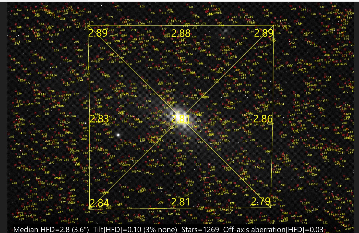
External analysis of a corrected frame: 1269 stars, median HFD 2.8, Tilt[HFD] 0.10 (3%, classified "none"), off-axis aberration 0.03. The per-tile median HFD values range only from 2.79 to 2.89 — extremely uniform.

M31 single frame with corner HFD values: TL 2.12, TR 2.14, Centre 2.16, BL 2.15, BR 2.17. The 0.05 variation across the field is negligible — within seeing-limited uniformity.
Reference Tables
Supported Tilt Plates
Any 3-point or 4-point tilt plate is supported — you only need to tell the advisory the plate's bolt-circle radius and screw thread. The values below are known reference figures. For plates not listed (or to confirm any value), check the manufacturer's website for a technical drawing, or measure the plate yourself (centre of plate to an adjustment screw = radius).
Plate |
Type |
Radius |
Thread/Pitch |
Notes |
|---|---|---|---|---|
WandererAstro ETA M54 |
3-point motorized |
64.0 mm |
0.50 mm/turn |
Automated Apply; radius/pitch auto-locked when detected |
ZWO Tilt Plate (M42/M48/M54/M68) |
3-point manual |
40.0 mm |
Check drawing |
Radius consistent across ZWO's thread sizes |
ToupTek M42 Tilter (Ø100 mm) |
4-point push/pull |
46.0 mm |
M4 push (0.70 mm) |
Screws on Ø92 mm circle; use the push-screw pitch |
Octopi tilt ring |
3-point manual |
Varies |
M3 (0.50 mm) |
Measure your specific unit |
Generic 3-/4-screw plate |
3- or 4-point manual |
Measure |
Measure/drawing |
Any plate works — supply radius + pitch |
Tip
Manufacturer technical drawings usually give the screw positions in mm from the optical axis — that distance is exactly the radius the advisory needs. If no drawing is available, a caliper measurement from the plate centre to a screw is accurate enough (the correction direction is unaffected by small radius errors, and the magnitude scales gently).
Thread pitch reference
Thread |
Pitch (mm/turn) |
|---|---|
M2.5 |
0.45 |
M3 |
0.50 |
M3 fine |
0.35 |
M4 |
0.70 |
M4 fine |
0.50 |
M5 |
0.80 |
M5 fine |
0.50 |
M6 |
1.00 |
Wanderer ETA |
0.50 |
ETA M54 specifications
Parameter |
Value |
|---|---|
Connection |
USB 2.0 Type-B, CH340, 19200 baud |
Travel per point |
0–1.200 mm |
Accuracy |
0.002 mm (2 µm) |
Motor resolution |
0.3 µm/step |
Bolt-circle radius |
64.0 mm |
Thread pitch |
0.50 mm/turn |
Weight |
470 g |
Operating temperature |
-25°C to 50°C |
Power |
USB 5V 0.5A |
INDI driver |
|
Device name |
"Wanderer ETA M54" |