
Guide
Introduction
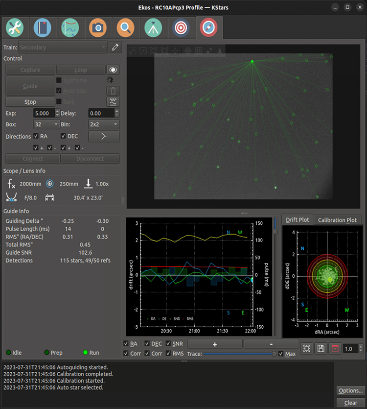
The Ekos Guide Module performs autoguiding using either the powerful built-in guider, or at your option, external guiding via PHD2 or lin_guider. Using the internal guiding, guider camera frames are captured and sent to Ekos for analysis. Depending on the deviations of the stars from their lock positions, guiding pulses corrections are sent to your mount’s RA and DEC axes motors. Most of the GUI options in the Guide Module are well documented so just hover your mouse over an item and a tooltip will popup with helpful information.
Setup
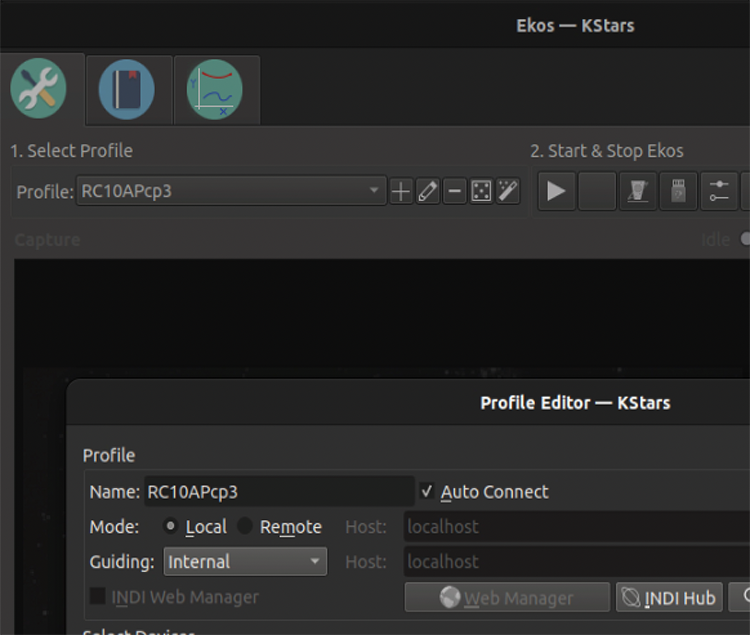
To perform guiding, you need (one time) to select a Guider in the Profile Editor for the profile you will be using. In the profile editor, choose Internal for the Ekos internal guider, or PHD2.
To perform guiding, you also need to set up your guiding optical train. This 2nd optical train is almost always different from the one you are using with capture/align/focus. See the image above for an example guider optical train configuration. Note that the telescope chosen is the guiding scope, which may be the same as your main telescope if you are using an OAG (off-axis-guiding) or ONAG guiding scheme. The camera selected is, of course, your guiding camera. The Guide Via should be your mount, assuming you are sending guide pulses directly to your mount, or the name of the ST4 device (e.g. your camera) should you be using ST4 guide pulses.
Please look at the main guider page shown at the start of this Guider section. There are many parameters that also can be adjusted, some of which are listed below.
Exposure: On the main guiding page you can adjust the guiding exposure time. After the guide-camera completes the exposure, the guide algorithm computes and sends the guide pulses to the mount, then it waits a user-configurable delay, and then then begins its next exposure.
Binning: Pixel binning for the guide image. It usually makes sense to bin the pixels 2x2. The algorithms can still find sub-pixel star positions and send proper guide pulses to the mount.
Box: This only is applicable to guide algorithms other than MultiStar, and MultiStar is the recommended guiding scheme. Size of the box enclosing the guide star. Select a suitable size that is neither too large or too small for the selected star.
Directions: Typically you want to keep all the directions boxes checked. Unchecking them will disable guiding in those directions. For instance it is possible to disable DEC guiding in the North direction.
Dark: Check this to enable dark-frame corrections to your guiding image. See below.
Clear Calibration: Check this to delete your calibration data. See the calibration section below.
Subframe, AutoStar: These only apply to guide algorithms other than MultiStar, and MultiStar is the recommended guiding scheme.

Calibration
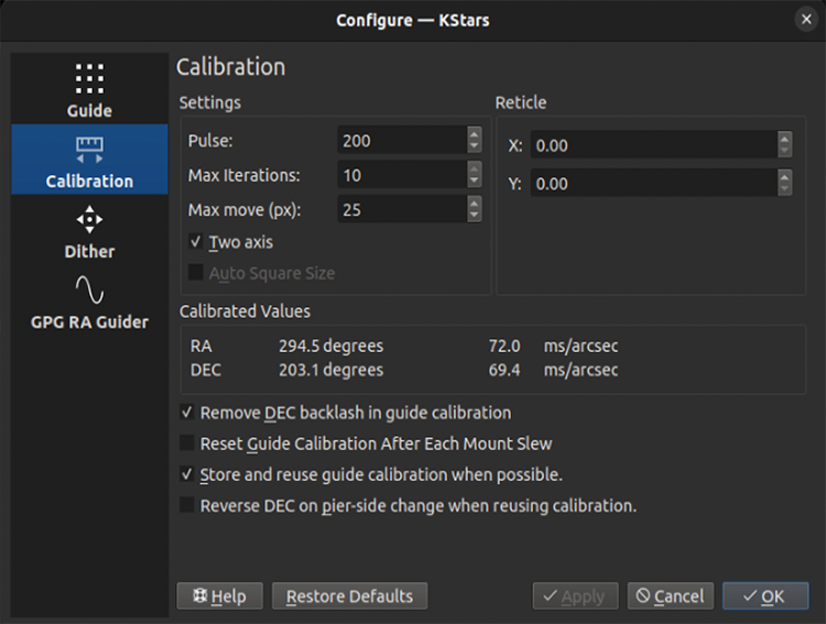
Autoguiding is a two-step process: Calibration & Guiding. Calibration is needed for the scheme to understand the camera’s orientation, relative to the RA and DEC axes, and also the effects of guide pulses (e.g. how much a 100ms RA guide pulse will typically move the RA axis). Once it estimates these values, the guider can correct the mount’s position effectively. You can see calibrated values for those parameters in the above image in the “Calibrated Values” section.
Similar to other guiders, we recommend that you carefully calibrate once, and then only re-calibrate when necessary. It is necessary to re-calibrate when the camera is moved (e.g. rotate) relative to the mount. It should not be necessary to calibrate every time you slew the mount. You should calibrate when pointing near the Meridian and along the Celestial Equator (probably just West of it). Guiding (and guide calibration) is problematic near the pole–it probably won’t work. This slide show contains good advice on how to calibrate the Internal Guider and/or PHD2.
The important options on the calibration options page (above) are:
Pulse Size: should be large enough to move your image a few pixels.
Re-using Calibration: There are two checkboxes related to keeping your calibration. We recommend checking “Store and re-use guide calibration when possible”, and un-checking “Reset Guide Calibration After Each Mount Slew”.
Reverse DEC...: It is also important to check or un-check (it is mount dependent) “Reverse DEC on pier-side change when re-using calibration”. To find out the right setting for your mount, you need to successfully calibrate on one pier side, make sure guiding is working well on that side, then switch to the other side. Guide for a minute or two. If DEC runs away, then you probably have the wrong setting for the “Reverse DEC…” checkbox.
Max Move, Iterations: We recommend you keep iterations large (e.g. 10) and Max Move large (e.g. 20+ pixels). This way you should get a good estimate of the guiding calibration parameters. Calibration should be something you do rarely, so it is best to take a little extra time and get right.To (re)calibrate, clear your calibration on the main guiding page, and then simply click on the Guide button. Note that if calibration was already completed successfully before, and you didn’t clear the calibration, and you are re-using calibrations, then the autoguiding process will begin immediately, otherwise, it will start the calibration process.
Ekos begins the calibration process by sending pulses to move the mount in RA and DEC. It pulses out the RA axis, then pulses it back in. After that it moves a little in DEC to clear and backlash that might exist, and then pulses out and back in for DEC. To view this graphically, click on the “Calibration Plot” subtab on the main guiding page.
Calibration Failures
Calibration can fail for a variety of reasons. To improve the chances of success, try the tips below.
Bad sky conditions. If your sky condition are not great, it may not be worth fighting guiding/calibration.
Guide camera focus.
Leave algorithm to the default value (
SEP
MultiStar
) in the Guide Option tab.Try the “Guide-Default” SEP star-detection parameters (in the Guide Option tab) and adjust them if necessary.
Better Polar Alignment: This is critical to the success of any astrophotography session. Use the Ekos Polar Alignment procedure in the Align module.
Set binning to 2x2: Binning improves SNR and is often very important to the success of the calibration and guiding procedures.Take dark frames to reduce noise.
Guiding
Once the calibration process is completed successfully, guiding begins automatically. The guiding performance is displayed in the
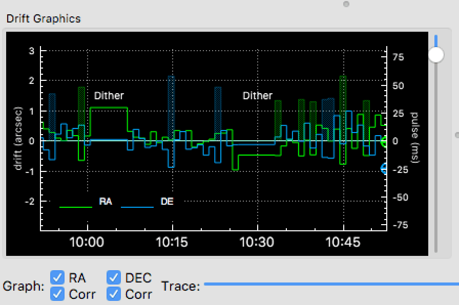
Drift Graphicsregion whereGreenreflects deviations in RA andBluedeviations in DEC. The colors of the RA/DE lines can be changed in KStars color scheme in KStars settings dialog. The vertical axis denotes the deviation in arcsecs from the lock position and the horizontal axis denotes time. You can hover over the line to get the exact deviation at this particular point in time. You can also zoom and drag/pan the graph to inspect a specific region of the graph. Another convenient place to examine guiding performance is in the Analyze tab.
There are two types of algorithms used in the internal guider, and you have choices of which variations to use for both. The first is the
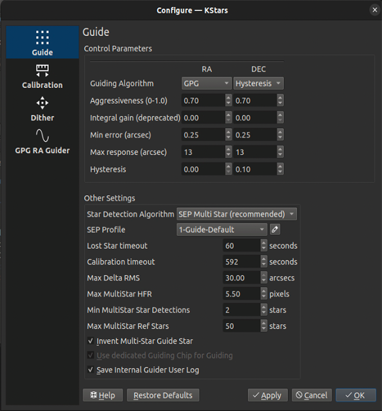
Star Detectionalgorithm. The guider captures images of the sky and automatically detects stars in these images. Once this is done, it can determine your mount’s drift in RA and DEC from its original position. The second type of algorithm is theGuiding Algorithmused to compute the RA and DEC guide pulses that should be sent to your mount to correct that drift.You can find star-detection algorithm choices in the Guide Settings page (above image) at the top of the
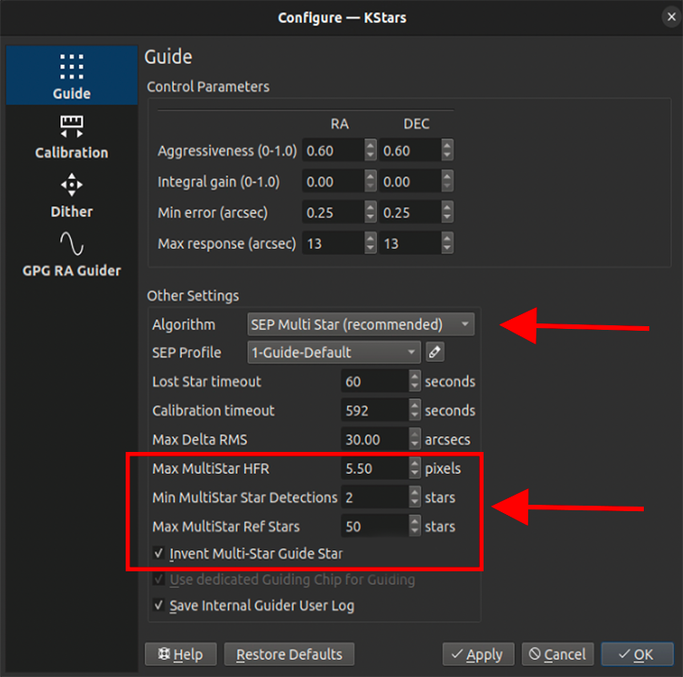
Other Settingssection. By far the most accurate is the (default) SEP MultiStar algorithm. It uses the detected position of many stars (in the above settings, up to 50) to determine its best estimate for the current drift. It is dependent on accurate star detection. Thus, it may be important to adjust star-detection parameters. Start with the default Guide-Default SEP profile, and optionally edit its parameters if you feel stars are not being detected accurately. Pretty much the only reason not to use SEP MultiStar would be if you can’t get your SEP star-detection to perform adequately.Guiding algorithm choices are made at the top of the settings page. You can choose separate algorithms for RA and DEC. Here are the possibilities:
Standard: The traditional proportional guide algorithm. It computes a pulse to correct the computed guide drift. The aggressiveness parameter decides what proportion of the error is corrected. Integral gain can be used but is not recommended. Errors smaller than MinError won’t be corrected. Max response limits the largest correction. The hysteresis parameter is not used.
Hysteresis: Hysteresis is like the standard algorithm but weights in the previous correction according to the hysteresis parameter.
Linear: This is similar to the PHD2 Lowpass2 algorithm. It computes the error pulses based on a short history of recent errors. This may be applicable to very stable mounts and is similar to the PHD2 LowPass2 algorithm.
GPG: (RA Only) The GPG algorithm tries to predict periodic error and linear drifts. It uses the aggressiveness, min and max parameters here, and more parameters on the separate GPG tab. It is very similar to the PHD2 PPEC algorithm. For technical details see this paper. There is more detail on GPG below.
AI Guider: (Experimental) Adds trained, mount-specific feed-forward predictions on top of the Standard algorithm, which keeps running underneath. It requires a one-time training session with the AI Guiding Assistant before it can be selected. See AI Guiding Assistant below.
A good starting choice is
StandardorHysteresis(with a 0.1 hysteresis parameter). You may want to useGPGfor RA, as it is probably the best performing algorithm for many mounts, however it is more complex to set up (see below).Linearis recommended for some high-performance mounts.Good advice in choosing parameters is available on the internet, e.g. from the above slideshow.
The main parameter choices you have are below. They are applicable to all the guiding algorithms.
Aggressiveness. This controls how quickly you want the guider to correct the error. Values of 0.5 to 0.7 are usually best (i.e. correcting roughly half the observed error). Unintuitively, it seems that correcting 100% of the error can cause poor performance as the guider may oscillate with overcorrections.
Min error. This controls the minimum deviation (in arc-seconds) for which a correction will be made. Adjusting this can avoid chasing the seeing.
Dithering
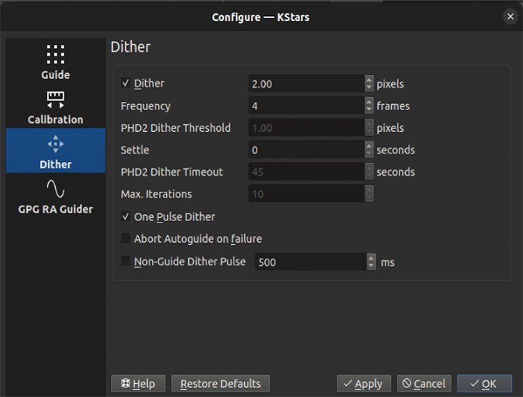
To enable automatic dithering between frames, make sure to check the
Dithercheckbox. By default, Ekos should dither (i.e. move) the guiding box by up to 3 pixels after every N frames captured in Ekos Capture Module. The motion duration and direction are randomized. Since the guiding performance can oscillate immediately after dithering, you can set the appropriateSettleduration to wait after dither is complete before resuming the capture process. In rare cases where the dithering process can get stuck in an endless loop, set the appropriateTimeoutto abort the process. But even if dithering fails, you can select whether this failure should terminate the autoguiding process or not. ToggleAbort Autoguide on failureto select the desired behavior.Dithering does not result in a long wander from the original target position. Ekos keeps track of the original and current target positions, and moves the target back towards the original target should the position have drifted too far.
One-pulse dithering is an interesting quicker option which sends a pulse to dither, but does not verify that the dither reached its desired location. It is possible that the dithering for any given dither isn’t as much as desired, but the overall effect should be good.
Non-guide dithering is also supported. This is useful when no guide camera is available or when performing short exposures. In this case, the mount can be commanded to dither in a random direction for up to the pulse specified in the
Non-Guide Dither Pulseoption.
Drift Graphics
The drift graphics is a very useful tool to monitor the guiding performance. It is a 2D plot of guiding deviations and corrections. By default, only the guiding deviations in RA and DE are displayed. The horizontal axis is the time in seconds since the autoguiding process was started while the vertical axis plots the guiding drift/deviation in arcsecs for each axis. Guiding corrections (pulses) can also be plotted in the same graph and you can enable them by checking the
Corrcheckbox below each Axis. The corrections are plotted as shaded areas in the background with the same color as that of the axis.You can pan and zoom the plot, and when hovering the mouse over the graph, a tooltip is displayed containing information about this specific point in time. It contains the guiding drift and any corrections made, in addition to the local time, this event was recorded. A vertical slider to the right of the image can be used to adjust the height of the secondary Y-axis for pulses corrections.
The
Tracehorizontal slider at the bottom can be used to scroll through the guide history. Alternatively, you can click theMaxcheckbox to lock the graph onto the latest point so that the drift graphics autoscrolls. The buttons to the right of the slider are used for autoscaling the graphs, exporting the guide data to a CSV file, clearing all the guide data, and for scaling the target in theDrift Plot. Furthermore, the guide graph includes a label to indicate when a dither occurred so the user knows guiding was not bad at those points.The colors of each axis can be customized in KStars Settings color scheme.
Drift Plot
A bulls-eye scatter plot can be used to gauge the accuracy of the overall guiding performance. It is composed of three concentric rings of varying radii with the central green ring having a default radius of 2 arcsecs. The last RMS value is plotted as
with its color reflecting which concentric ring it falls within. You can change the radius of the innermost green circle by adjusting the drift plot accuracy.
Guiding with Multiple Stars
In standard guiding the system selects a guiding star. In non-MultiStar systems, the measured movements of that star relative to its original positional measurements are converted to RA and DEC offsets which are the guiding drift errors. In MultiStar guiding the system selects many reference stars and measures all their offsets relative to their initial positions. The guiding error is computed as the median displacement of the individual reference stars from their original positions. The magic the system needs to perform is to find this noisy 2-dimensional pattern of reference stars in the guide image, but finding this pattern is more robust than finding a single guide star that may have moved significantly or may not have been detected at all. We recommended you choose this way to guide by selecting the guide Algorithm SEP Multi Star.
There are a few options you may wish to consider. Max MultiStar Ref Stars is the maximum number of reference stars the system can use. The main reason to limit this is computation cost, thought it is not a very expensive computation. 50 is a good choice. The setting Min MultiStar Star Detections tells the system to fallback to a single guide star if there are fewer than that many star detections. Invent Multi-Star Guide Star should be left checked, and Max MultiStar HFR is an old parameter that likely has little effect anymore.
Guiding with GPG
With GPG guiding, the internal guider uses predictive and adaptive guiding for the RA axis. This adaptively models the periodic error of the mount, and adds its predicted contribution to each guide pulse.
The main settings to consider are Major Period and Estimate Period. If you know the worm period for your mount, perhaps by examining this table, then uncheck Estimate Period and enter your known Major Period. If not, then check Estimate Period. Intra-frame dark guiding can be used to “spread out the GPG prediction. For instance, if you guide at 5s, you can set the dark guiding interval to 1s and its prediction is pulsed every second, but the guiding drift correction would be sent every 5s. In this way, it outputs the predicted corrections much faster than the guide camera exposure rate, effectively performing periodic error correction and allowing longer guide camera exposures. All the other parameters are best left to defaults.

Streaming Guide

In streaming guide mode the internal guider captures guide frames from the camera’s continuous video stream instead of taking a separate exposure for each guide frame. Frames arrive continuously and the guider always works from the most recent one (“latest frame wins”), which removes the readout/download dead time between exposures. The result is a faster, lower-latency guide cadence — useful for the higher guide rates (roughly 2–5 Hz) that some mounts, especially harmonic/strain-wave drives, benefit from.
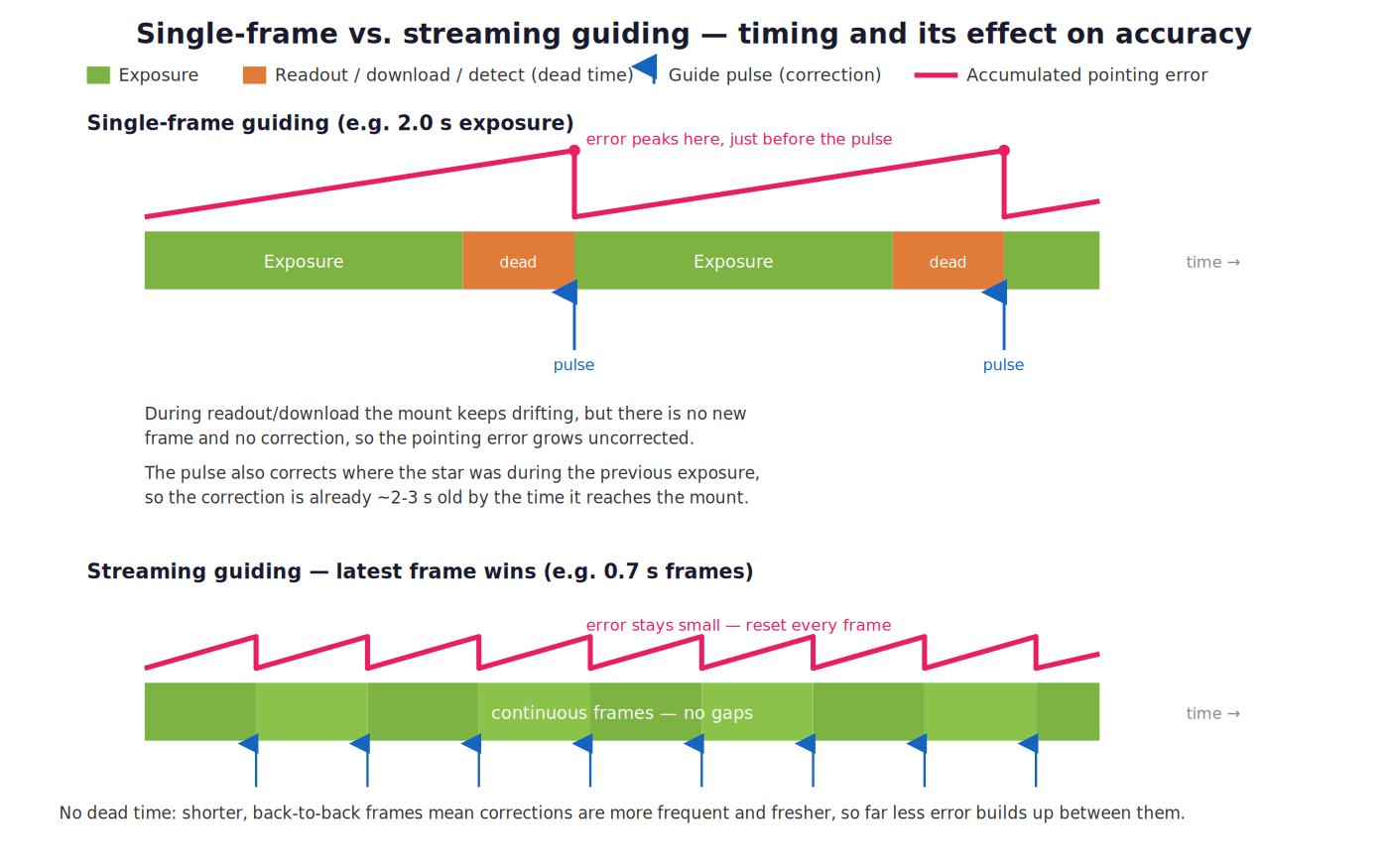
Why streaming helps. In single-frame guiding (top) each exposure is followed by readout/download/detection dead time, during which the mount keeps drifting with no new measurement and no correction, so the pointing error grows uncorrected and peaks just before each pulse. The pulse itself is based on the star position measured during the previous exposure, so the correction is already a couple of seconds old by the time it reaches the mount. Streaming guiding (bottom) delivers frames back-to-back with no dead time (“latest frame wins”), so corrections are more frequent and fresher and far less error accumulates between them.
Streaming affects only how frames are delivered to the guider; the guiding algorithms, calibration, dithering, and lost-star handling all behave as usual. It works with the Standard/MultiStar and GPG algorithms as well as the experimental AI Guider.
Requirements
The internal guider (streaming is not used with external PHD2).
A guide camera that supports INDI video streaming.
A completed, successful calibration — calibration itself always runs with single frames (see below).
Enabling Streaming Guide
Check the Stream box on the main Guide page, next to the Exp and Delay controls, before you start guiding.
The guide Exp (exposure), Gain, and Bin controls apply to the streamed frames exactly as they do to single exposures; a gain change takes effect immediately while streaming.
备注
Calibration always runs with single frames for stability, regardless of the Stream setting. Streaming begins automatically only once guiding starts (and only if Stream is checked), and stops again when guiding stops. This keeps calibration clean and settled while still giving you the streamed, dead-time-free cadence during guiding.
16-bit Stream Depth (INDI)

The bit depth of the video stream is set on the camera driver, not in the Guide module. Open the INDI Control Panel, select your guide camera, and go to the Streaming tab:
Set Stream Depth to 16-bit. This is highly recommended for guiding: 16-bit (RAW16) frames preserve the full sensor bit depth, which gives better centroiding and faint-star detection than 8-bit.
Make sure the Encoder is set to RAW (not MJPEG).
Save the setting to the driver configuration (from the Options tab) so it persists across sessions — otherwise the stream may revert to 8-bit the next time the camera connects.
Examples

Streaming guide with the GPG algorithm on RA and Linear on DEC, at 0.7 s exposure and 2×2 binning on a harmonic-drive mount — total RMS around 0.46″ with 100 detected stars.

Streaming guide combined with the experimental AI Guider. Because streaming supplies frames with no inter-frame dead time, it pairs naturally with the higher guide rates that harmonic drives and the AI predictor work best at.
Notes and Limitations
Dark-frame subtraction works in streaming mode. The Dark checkbox applies a matched dark frame (and defect map) to each streamed guide frame, just as in single-frame guiding — useful for removing amplifier glow or hot pixels on some guide sensors. As always, a suitable dark must exist in the Dark Library for the current guide exposure, gain, and binning (see Dark Frames). Note that removing a smooth glow gradient requires actual dark subtraction: set the Dark Library to Prefer Darks rather than Prefer Defects, since the defect map only repairs isolated hot/cold pixels and will not remove glow.
Streaming requires a camera and driver with working INDI video streaming; if the camera does not support it, the guider falls back to single-frame captures.
As with any guide configuration, verify your results: streaming changes the cadence, not the fundamentals, so good polar alignment, balance, and calibration still matter most.
AI Guiding Assistant (Experimental)

The AI Guiding Assistant adds a trained, mount-specific feed-forward predictor to the internal guider. After a one-time training session, the AI learns the repeatable part of your mount’s tracking error — such as periodic error and slow drift — and adds a predicted correction to each guide pulse before the error becomes visible in the guide image. The standard guiding algorithm keeps running underneath at all times and corrects whatever the prediction misses.
The entry point is the AI Guiding (Experimental) menu button on the main Guide page, just below Clear Calibration. It offers two actions: AI Guiding Assistant…, which opens the data-collection wizard described below, and Load Weights…, which loads a previously trained model file. This feature is unrelated to the AI Assistant (MCP) interface, which connects KStars to external chat assistants.
警告
The AI Guiding Assistant is an experimental feature under active development. Trained models are tied to your specific mount, camera, and guide settings. Always verify your guiding performance after enabling it, and be prepared to switch back to the Standard or GPG algorithms if your results are not better with the AI.
Expectations and Prerequisites
Please read this part carefully before investing time in training a model — it will save you from disappointment later.
警告
AI guiding augments a well-functioning guiding setup — it does not repair a poorly functioning one. It predicts the repeatable part of your mount’s error and layers that prediction on top of the standard guiding algorithm. It will not fix:
poor polar alignment,
imbalance, cable drag, or differential flexure,
wind gusts, vibrations, or bad seeing,
a mount or guide system that is not already well tuned.
None of these are repeatable errors, so no amount of training can predict them. If standard guiding does not work well on your system, fix that first. The improvement from AI guiding varies considerably from mount to mount, and on some mounts you may see no measurable benefit at all.
Before running the assistant, make sure that:
You are using the internal guider, with a working guide camera and a completed, successful calibration.
Ordinary guiding with the Standard algorithm already works reliably on your setup.
Your mount is well polar-aligned, balanced, and free of cable snags.
You know your mount’s drive type: worm gear (most equatorial mounts), harmonic/strain-wave drive, or direct drive.
Your guide exposure is the one you intend to keep using: the model is trained and locked to the guide exposure, binning, and guide settings used during data collection.
You have 20–45 minutes of clear, reasonably steady sky to spend on data collection, depending on the mount type.
Data Collection with the AI Guiding Assistant
Training a model starts with a system identification session: the assistant points the mount at a few positions in the sky and records how the guide star drifts, both with guiding running and with guiding deliberately paused (“free drift”), so that the mount’s raw error signature can be measured. Click AI Guiding (Experimental) → AI Guiding Assistant… on the Guide page to start the wizard.

Page 1 — Mount Identification. Verify the detected mount type: Worm Gear, Harmonic Drive, or Direct Drive. The wizard also recommends a guide exposure per drive type — 2.0 s for worm gears, 0.5–1.0 s for harmonic drives (depending on guide star signal), and 1.0–3.0 s for direct drives. Set your exposure before proceeding: the trained model is locked to it.
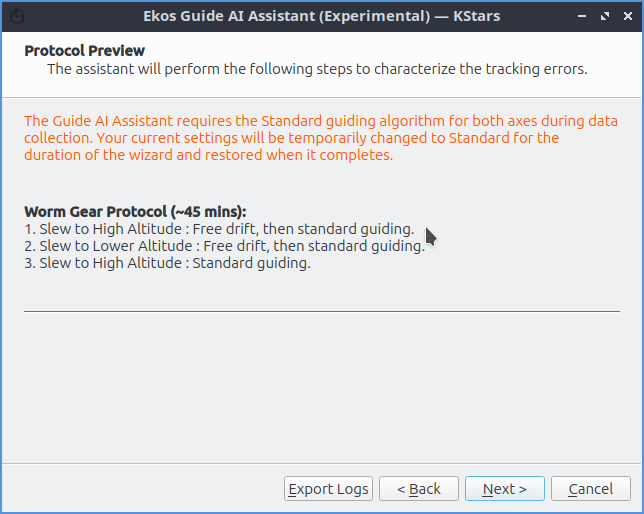
Page 2 — Protocol Preview. The wizard shows the measurement protocol it is about to run. During data collection your guiding settings are temporarily switched to the Standard algorithm on both axes with all guide directions enabled; your original settings are restored when the wizard finishes. The protocol depends on the mount type:
Worm Gear (~45 minutes): three pointings at high, lower, and high altitude, each combining standard guiding with several minutes of free drift. The long free-drift phases capture roughly three full worm cycles, which is what allows the periodic error to be measured.
Harmonic Drive (~35 minutes): free drift and standard guiding at two pointings, plus a series of short pulse-response tests (50, 100, and 200 ms pulses in all four directions) that measure how the drive reacts to corrections.
Direct Drive (~20 minutes): short guiding and free-drift phases at three different altitudes.
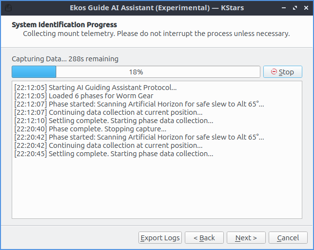
Page 3 — System Identification Progress. The assistant slews, guides, and drifts on its own. Leave the system alone while it runs — interrupting the process invalidates the affected phase. Use Stop only if something goes wrong.

Page 4 — Data Collection Complete. The measured data is saved, and
you choose how to train the model: Train in EkosLive uploads
the data to EkosLive Cloud and returns a ready-to-use model (next
section), while Export for offline training writes a
sysid_data.json file for the Python trainer (see
below).
Training via EkosLive
The easiest way to train the model is with an EkosLive account: click Train in EkosLive
on wizard page 4. The data is uploaded, the model is trained in the
cloud, and the resulting weights are automatically saved (as
ai_guider_weights.json in the KStars data folder,
~/.local/share/kstars/ on Linux) and set as the active weights
file — no further steps are needed.
备注
The uploaded system-identification data contains no sky coordinates: only altitude, azimuth, and parallactic angle, together with pixel drift measurements, star signal-to-noise ratios, and the guide pulses that were sent. It does, however, include your mount’s name and camera device names. If you prefer not to upload anything, use offline training instead — it produces identical weights.
Training the Model Offline
You do not need EkosLive to train a model — the trainer is a small set of Python scripts that runs on any ordinary computer. Training uses only the CPU and finishes in under ten minutes; no GPU is required.
On wizard page 4, click Export for offline training and save
sysid_data.json.Copy the file to the computer where you want to train (it can be the observatory computer itself, but a desktop or laptop is usually more convenient).
Get the trainer scripts from the
kstars/ekos/guide/offlinetrainer/directory of the KStars source repository.In that directory, create a Python environment and run the trainer:
python3 -m venv venv
source venv/bin/activate
pip install numpy scipy torch
python train.py --sysid-data ./sysid_data.json --output ./weights.json
The trainer auto-detects your mount type from the data and picks the
matching model. Should the detection ever be wrong, it can be overridden
with --mount-type WORM_GEAR|HARMONIC_DRIVE|DIRECT_DRIVE.
Finally, copy the resulting weights.json back to the observatory
computer and load it in KStars via AI Guiding (Experimental)
→ Load Weights… on the Guide page (or set the
Weights File on the AI Guider options page). The
weights are applied the next time guiding starts.
Activating AI Guiding and Options

With a weights file loaded, select AI Guider as the guiding algorithm for RA and/or DEC in the guider options, and start guiding as usual. The AI-related settings live on the AI Guider page of the guide settings dialog:
Weights File: path to the trained model weights (JSON).
AI Prediction Gain (default 0.5): how strongly the AI prediction is blended into the guide pulses. 0.0 ignores the AI entirely; 1.0 applies its full prediction. Start at the default and increase gradually if guiding improves.
Scale Down Proportional Gain During AI Correction (default off): reduces the standard proportional response by up to half when the AI is highly confident, to avoid the two controllers over-correcting the same error.
Enable Predictive Dark Guiding (default off): keeps emitting predicted corrections during gaps in guide star measurements — dither settling, autofocus runs, or camera downloads — by extrapolating the periodic error forward in time.
Dark Guiding Interval (default 1.0 s): seconds between predicted pulses when no guide-star measurement is available.
备注
A weights file only works with the guide settings it was trained with. When guiding starts, the file’s fingerprint is checked against your current guide exposure, binning, gains, minimum/maximum pulse, and hysteresis settings. On a mismatch, guiding aborts with an explanatory message — either restore the settings you used during data collection, re-run the assistant to train new weights, or switch the algorithm back to Standard.
Monitoring AI Guiding
The guide state display shows what the AI is doing. After guiding starts, the AI is in a warm-up phase (shown as Warm up) while it synchronizes its model with the live mount — about 50 guide frames for worm gears, 30 for harmonic drives, and 10 for direct drives. During warm-up, guiding is handled entirely by the standard algorithm. Once its predictions are verified against real measurements, the AI becomes Active and its corrections are blended in.
The blend is weighted by a live confidence score. Confidence requires a reasonably bright guide star (it reaches its maximum around a signal-to-noise ratio of 30 and drops to zero below 10) and falls whenever the AI’s predictions stop matching what the mount actually does. When confidence is low, the standard guiding algorithm does most of the work — an underperforming model degrades gracefully instead of ruining your subframes.
Several safeguards apply at all times: every pulse respects your configured maximum pulse limits plus a hard 5-second ceiling; AI predictions are suspended during dithering; a meridian flip resets the AI’s internal state for re-warm-up; and a lost guide star triggers the guider’s normal reacquisition logic.
How It Works
A mount’s tracking error has two parts. The repeatable part comes from its mechanics — the worm gear’s periodic error, gear imperfections, atmospheric refraction, and the slow drift from residual polar-alignment error. The random part comes from seeing, wind, and measurement noise. A conventional guider is purely reactive: it can only correct an error after the star has already moved. A feed-forward guider, by contrast, predicts the repeatable part and cancels it as it happens — but it can do that only for errors that repeat, which is why data collection matters and why the random part remains the standard algorithm’s job.
The AI Guider is deliberately conservative in how it uses its predictions. Each guide cycle, the standard controller computes its normal correction from the measured drift. In parallel, the AI model computes a predicted correction, which is scaled by the live confidence score and your prediction gain, and added on top. The summed pulse then passes through the safety clamps before being sent to the mount. If the AI contributes nothing useful, its term simply fades to zero and you are left with plain standard guiding.
The model itself is chosen to match the mount’s physics rather than being one large neural network:
Worm gear mounts use a physics model of the periodic error, refraction, and polar drift, with its phase tracked live while guiding, plus a tiny neural network (about 200 parameters) that learns the leftover, mount-specific residuals.
Harmonic drive mounts use a Kalman-filter model of the drive’s spring wind-up and periodic error, with a small neural network correcting its predictions.
Direct drive mounts have almost no mechanical error, so only refraction and drift are modeled analytically — no neural network is involved.
Troubleshooting and Notes
Guiding aborts immediately with a weights error. The weights file failed to load or its fingerprint does not match your current guide settings. Restore the settings used during data collection, retrain, or switch the algorithm back to Standard.
The AI stays in warm-up or never becomes active. This is usually caused by a faint guide star (low signal-to-noise) or by predictions that do not match your mount’s current behavior. Guiding continues normally on the standard algorithm either way; consider retraining under better conditions.
No visible improvement. This is a realistic outcome on some mounts — especially ones with little periodic error or dominated by non-repeatable errors. Compare a few guiding sessions with the AI enabled and disabled under similar conditions before drawing conclusions.
When to retrain: after changing the guide camera, guide exposure, binning, guide optical train, mount, or any fingerprinted guide setting — and whenever guiding performance degrades noticeably after a remesh or mechanical adjustment.
Reporting problems: the wizard’s Export Logs button bundles the AI debug logs and guide logs into a single archive that you can attach to a bug report or forum post.
Dark Frames
Dark frames can be helpful to reduce noise in your guide frames. If you choose to use this option, then it is recommended that you take dark frames before you begin your calibration or guiding procedure. To take a dark frame, check the
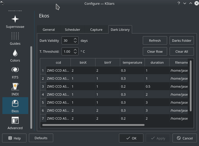
Darkcheckbox and then clickCapture. For the first time this is performed, Ekos will ask you about your camera shutter. If your camera does not have a shutter, then Ekos will warn you anytime you take a dark frame to cover your camera/telescope before proceeding with the capture. On the other hand, if the camera already includes a shutter, then Ekos will directly proceed with taking the dark frame. All dark frames are automatically saved to Ekos Dark Frame Library. By default, the Dark Library keeps reusing dark frames for 30 days after which it will capture new dark frames. This value is configurable and can be adjusted in Ekos settings in the KStars settings dialog.
It is recommended to take dark frames covering several binning and exposure values so that they may be reused transparently by Ekos whenever needed.
PHD2 Support
You can opt to select external PHD2 application to perform guiding instead of the built-in guider.
If PHD2 is selected, the
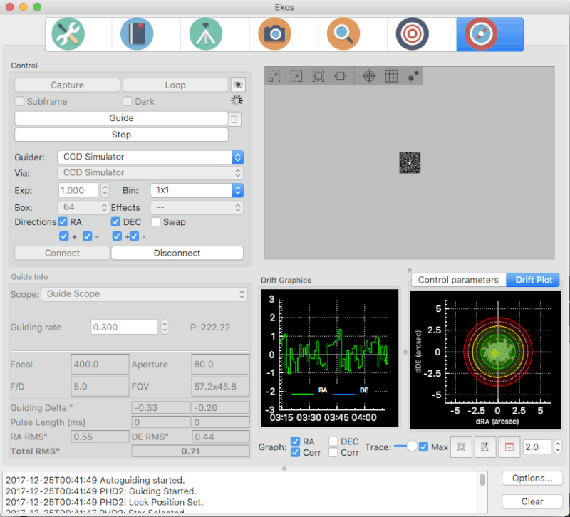
ConnectandDisconnectbuttons are enabled to allow you to establish a connection with the PHD2 server. You can control PHD2 exposure and DEC guide settings. When clickingGuide, PHD2 should perform all the required actions to start the guiding process. PHD2 must be started and configured before Ekos.After launching PHD2, select your INDI equipment and set their options. From Ekos, connect to PHD2 by clicking the
Connectbutton. On startup, Ekos will attempt to automatically connect to PHD2. Once the connection is established, you may begin the guiding immediately by click on theGuidebutton. PHD2 performs calibration if necessary. If dithering is selected, PHD2 is commanded to dither given the offset pixels indicated, and once guiding is settled and stable, the capture process in Ekos resumes.
Guiding Logs
Ekos’ internal guider saves a CSV guide log in PHD2 format data that can be useful for analysis of the mount’s performance. In Linux this is stored under
~/.local/share/kstars/guidelogs/. This log is only available when using Ekos’ internal guider. It should be compatible with PHD2’s guide log viewer.